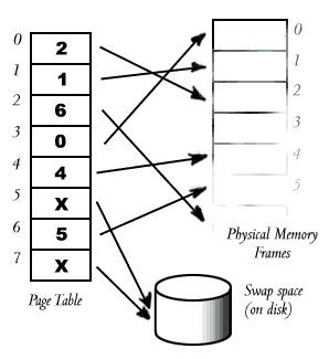
In the simplest scheme, there is a single table (for each process), which is an array, one element for each of the process's pages, each of which points to a frame.
When the processor is in user mode and generates a virtual address for a memory access, the address is fed through the MMU, which works out which page the memory address refers to, looks up the appropriate frame, and creates a physical address, based on the address of the frame and the position within the page.
For example:

Every memory reference by the processor goes through the page table, and is mapped from a virtual address to a physical address.
Let's assume that the page size is 1KB. If the processor attempted to access memory location 10, this would fall within the first page, page #0, which is mapped to frame #2. Frame #2 starts at location (1K × 2 = 2048), so the processor's virtual memory request for location 10 is directed to physical memory location (2048 + 10) = 2049.
In the diagram, we see that pages 5 and 7 are mapped out to disk. If the current process attempts to access any location within either of these pages, a page fault will occur, causing the operating system to take some action (most likely to swap in the faulted page and restart the process).
Pages are almost always a power of two bytes in size (like 512bytes, or 1024bytes, or 2048bytes). This means that every virtual address may be split easily into two parts: the page number and the offset.
For example, one very old computer architecture, the PDP-11, had 16-bit addresses, and a page size of 8K (requiring 13 bits for the page offset). Its (virtual) address format therefore looked like this:

The top 3 bits indicated the page number, and the bottom 13 bits (the offset) indicated the position within the page. With 3 bits for the page number, the PDP-11 allowed 8 pages per process.
The PDP-11 kept its page table entirely in on-chip registers, so it could perform the lookup quickly. This was possible because the page table was small.
Look at an example of page mapping on the PDP-11.
Remember that in a multitasking system the processor often switches between threads. Switching between threads in different processes requires switching page tables (since each process has its own virtual address space). If the table is very large, and must be loaded into CPU registers at every context switch, this seriously increases the overhead of context switches. (Switching between threads in the same process can be much faster than switching between threads in different processes.)
Generally, page tables are held in main memory, simply because they are too large to be held in fast processor registers. The processor contains only a page table base register, which points to the start of the page table in memory. When the OS switches between processes, it simply changes the value of the PTBR, and the processor starts using the page table for the new process.
The page table is composed of many page table entries (PTEs).
But! Page tables in physical memory still have two important problems: